
![]()
![]()
![]()
![]()
![]()
![]()
![]()
![]()
![]()
![]()
![]()
![]()
![]()
![]()
![]()
![]()
![]()
![]()
![]()
![]()
![]()
ECS 1-Second Pendulum Master Clocks
|
Within this page, fast-find:- |
|
|
|
|
|
|
|
|
|
|
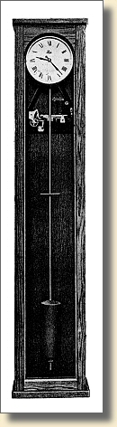
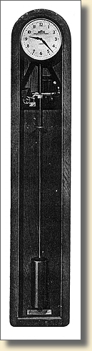
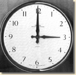
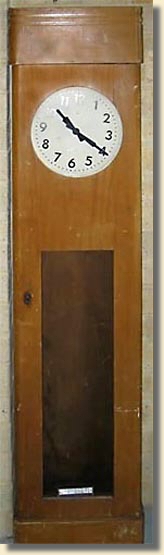
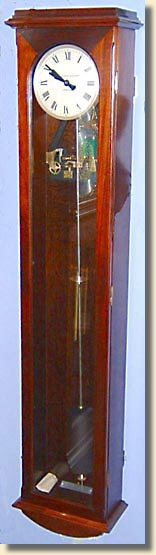
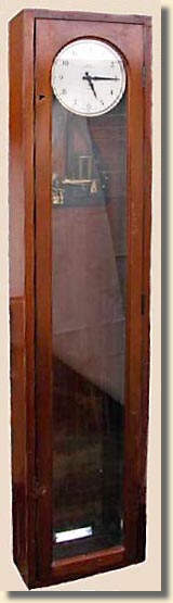
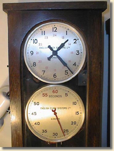
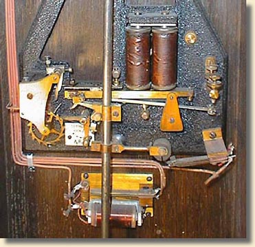
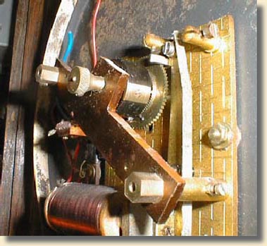
The clocks have a 1-second Invar pendulum with a 17 pound cylindrical bob, and are impulsed every 30 seconds by an electrically reset gravity arm. There are two standard case styles; flat-top (Fig. 1) and round-top (Fig. 2). The movement is built on a cast iron A-frame (Fig. 3). There is a 15-tooth count wheel, two resetting coils mounted vertically above the gravity arm, a capacitor (with a spark quench resistor behind the casting) and a current setting rheostat.
|
|
|
Fig. 1 Flat-top case style |
Fig. 2 Round-top case style |
Fig. 3
Cast iron A-frame movement
CLOCK SERIAL NUMBERS & DATING
All clocks are serial numbered on the A.R.N. plate mounted on the movement casting. There are 5 groups of serial numbers:
- sub-1000 series (Sample and dating too vague to give dates)
- 1000 series up to approximately mid 1950
- 10,000 series up to late 1954
- 20,000 series up to mid 1957
- 30,000 series last recorded clock mid 1966
As the earliest recorded mention of the master clock is in an advertisement in June 1939, production may well have started just before World War II broke out, but would almost certainly have been reduced or suspended during the war. Dating of the early clocks (sub-1000 and 1000 series) is almost impossible as they were not dated during manufacture. There is a published report regarding a clock with serial number 196 giving a purchase date of 1945/6 and a possible manufacture date of 1938, but the latter is not a verifiable date. Two examples in the 1000 series have installation dates recorded in pencil on the inside surface of the pilot dial (1948 and 1950), and one clock's serial number is shown on a dated technical drawing (1949). Until evidence to the contrary is found, 1945 has been taken as the probable start of the main production and marketing.
The serial numbers are not a true reflection of the actual number of clocks made as numbering recommenced each time a new series was started. Some obvious design changes happened at serial number boundaries, and some design changes were made during a series. The reasons for the numbering changes are not always obvious.
From the latter part of the 10,000 series onwards the movement of the pilot dial was given a date code that was stamped into the rectangular brass plate on which the movement is constructed. This becomes the prime source of dating information. Initially this code was in the form of two digits for the year, followed by one or two digits for the month, e.g. 547 gives July 1954 and 5512 gives December 1955. Around 1961 or 1962 this code changed to become one or two digits for the month and one digit for the year within the 1960 decade. e.g. 113 is November 1963 and 54 is May 1964.
Even this dating evidence is not too accurate as the slave movements were also produced for individual slave dials and for other clocks apart from the master clocks, and it is suspected that slave movements were dated at the time that a batch was manufactured, but were not taken from stock in strict rotation when assembling the master clocks. Thus, a clock with a higher serial number may have an earlier dated pilot movement than an adjacent lower serial number clock. This gives an uneven distribution to the production pattern. (See Chart 1).
DESIGN CHANGES
1). There were two major design changes for which dates can be established.
a). Case and dial style.
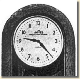
The first change coincides with the start of the 20,000 series in late 1954 and is purely cosmetic. The standard case style is changed from flat-top to round-top (see Figs 1& 2 above); the dial is given Arabic numerals instead of Roman, with a painted background instead of silvered; and the hands are changed to a more 'modern', sleeker shape (Figs. 4 & 5). An intermediate form of hand is also used from this time onwards where a tail from the original design is retained, presumably as a counterbalance, along with the main part of the new design (Fig. 6).
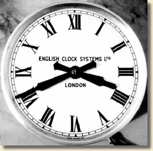
Fig. 4
Old style dial
|
|
|
Fig. 5 New style dial & hands |
Fig. 6 Intermediate style dial & hands |
b). Contacts.
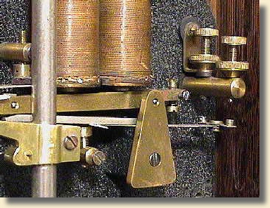
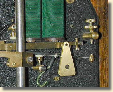
The other major change was technical, occurring part-way through the 30,000 series towards the end of 1959, where the contacting arrangements were changed from double-contact to single-contact. In the double-contact design (Fig. 7), the moving contact on the armature bridges two fixed contacts to complete the circuit. This obviated the need for a flexible wire connection from the armature to the frame of the clock. A flexible wire could fracture, or could stiffen over time and impede the action. The original double-contact arrangement had always been a source of unreliability as the two sets of contacts are both required to make a reliable connection to complete the resetting circuit, and therefore the contact pressure is shared between them. In the later single-contact design (Fig. 8), the armature became part of the circuit and a flexible connection was then required back to the baseplate. Contact pressure was thus doubled, giving a more reliable contact.
|
|
|
Fig. 7 Double-contact & Brass 'L' link |
Fig. 8 Single-contact |
2). There were also a number of more minor changes, none of which have yet been definitely dated or related to changes in serial number series. These are:
a). Connection to double-contact pillar.
Where clocks have the double-contact arrangement, both contacts are mounted on a single pillar and are insulated from each other and from the baseplate. The rear contact is connected through the baseplate via an insulated bush and a brass 'L' shaped link (See Fig. 7). Towards the end of the 10,000 series, the brass 'L' link gives way to a wire link.
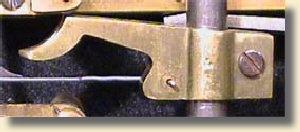
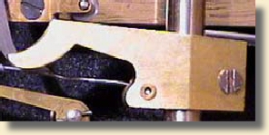
b). Impulse pallet form.
Up to around the end of the 10,000 series, the impulse pallet was parallel sided with a curved form around the pendulum rod (Fig. 9). Later pallets were of a diamond plan form with the widest part of the pallet around the rod (Fig. 10). There does seem to be a slight difference in the profile of the impulse slope between examples, with some being steeper than others (Fig 11), but this has not been researched in detail as it would involve at least a closely matching photograph, if not personal examination, of every recorded clock.
|
|
|
Fig . 9 Impulse pallet up to the end of the 10,000 series |
Fig. 10 Impulse pallet 20,000 & 30,000 series |
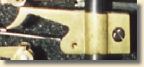
Fig 11
Impulse pallet 10092 - example of a steeper slope
c). Pilot dial movements.
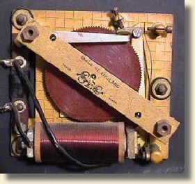
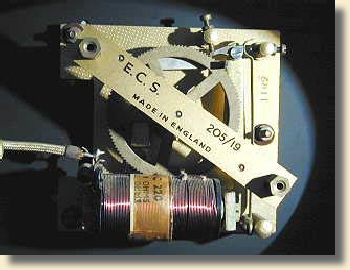
Early pilot dial movements have a solid composition index wheel (Fig. 12). This style has only been recorded in two clocks, 1006/S & 1021/S, both dating to pre-1950. These early movements also have "SEC" printed on the bridge plate as the movement maker, and the type number is stamped into the square brass plate. Later movements from around the start of the 1950s have a crossed out brass wheel and are printed with ECS and the type number on the bridge plate (Fig.13). All slave movements were made and supplied by Smiths English Clocks Ltd.
|
|
|
Fig. 12 Early slave - solid composition wheel (Type 205/19] |
Fig. 13 Later slave - Brass crossed out wheel (also Type 205/19) |
Most clocks in the survey sample contain a pilot dial with a movement of type number 205/19. There is a period from January 1954 to September 1958 when dials were supplied with a type number 205/12 movement. ECS specifications for type 205/12 have been found, but not for the more common 205/19. From survey responses, both types appear similar and were suitable for a dial up to 12 inches diameter. Specifications of slave movements are given in the section on slave dials.
A summary of all the major design changes and dates is given in Chart 2.
SPECIAL CABINETS
A few clocks have appeared with unusual or special cases.
|
|
|
|
|
Two clocks have appeared in the survey sample with this cabinet made in cedar wood. Both clocks are in Australia, and were probably cased there. |
A superb mahogany cabinet with a decorative moulding at the top, and a curved base. Although no history exists, this is a special cabinet for display in an important location. |
Two clocks have been found with this style of cabinet. Both clocks have serial numbers in the 30,000 series, so should have the standard round-top cabinet. This cabinet style is reminiscent of the early flat-top cabinet, but the door fits within the side panels, not in front of them. |
MOVEMENT LAYOUT
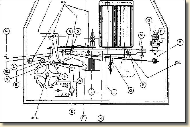
Fig. 14
General layout of master movement showing positions of roller 'D', pallet 'E' and jewel 'S'
with pendulum at rest.
(From an ECS drawing).
SPECIAL EXAMPLES
Two variations from the normal pattern of clock have emerged from the survey.
1). Mercury Switch.
There are three clocks recorded, all in South Africa, whose contacts have been replaced by a mercury filled glass tilt switch mounted on the right-hand end of the gravity arm.
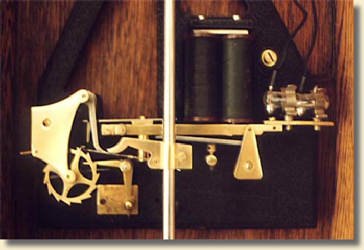
Fig. 15
Mercury switch modification
These modifications were carried out by the ECS agent in South Africa, United Clocks Sales (PTY) Ltd., from around 1960. Several master clocks in South Africa were modified, although only three have been recorded in the survey.
2). Master clock with seconds dial.
Two clocks have been recorded in the UK with a suffix to the serial number of '/S'. These are both early flat-top case clocks, with serial numbers 1006/S and 1021/S, probably dating to the second half of the 1940s. The suffix 'S' denotes a clock with a seconds pilot dial (Fig. 16).
Seconds pulses are derived by means of an additional short arm fixed to the pendulum rod projecting to the right and level with the bottom of the frame casting. This carries an almost circular horse-shoe magnet below which is a soft iron armature attached to a contact set which is mounted on the frame casting with a screw and two steady pins (Fig. 17). The magnet passes over the armature and causes the contacts to close at the centre of the pendulum's swing, so giving true seconds pulses of short duration. There is an auxiliary relay mounted on the backboard of the case below the frame casting.
|
|
|
Fig. 16 Clock 1006/S with seconds slave |
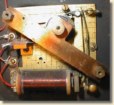
Fig. 17 Seconds movement |
The arbor of the seconds pilot dial carries an insulating drum with a conducting sector (Figs. 18 & 19). As the drum rotates with the seconds arbor, a pair of fixed contacts wipe the drum and are shorted together by the conducting sector for a 5 second period each minute. The numerals 55 and 60 on the seconds dial are painted red, with all other numerals in black, and the 5-second sector relates to the last 5 seconds of the minute. The seconds hand together with the drum with the contact sector can be rotated separately from the indexing wheel, and locked in any position, so that the seconds hand matches the indexing of the minute hand on the main dial.
|
|
|
Fig. 18 Seconds pilot movement (type 205/18) |
Fig. 19 Seconds pilot movement, showing insulating drum & conducting sector |
The wiring in this clock is not original or complete, so the function of the auxiliary relay and 5-second contacts is conjecture. A possible scenario is that the wiping contact allowed the auxiliary relay to operate once per second for 5 seconds per minute as shown in Fig. 20. This would give 6 closures per minute.
Only one of these two '/S' clocks is complete with the seconds contacts and dial, the other having been altered back to a standard form. Empty screw holes in the A-frame casting and in the case attest to its original form being similar to the complete example.
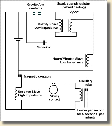
Fig. 20
Possible circuit for seconds dial and auxiliary relay
SERIAL NUMBER ANOMALIES
There are three clocks which do not fit the pattern of the rest of the survey sample:
Serial number 1238 is an early double contact movement, but is in a post-1955 style round-top case with its original Roman style pilot dial which carries a penciled installation date of June 1950. Perhaps a style-conscious owner changed the case.
Serial number 30408 is a single contact movement with an Arabic pilot dial marked with a date code for November 1963, but mounted in an early flat-top case. The date code on the pilot dial and the movement's serial number are contemporary. This is an isolated example of a flat-top case containing a later movement, and could be due to a replacement movement and pilot dial in an existing case.
Serial number 30129 is a single contact movement in a round-top case with an Arabic pilot dial. The slave date code and the clock serial number are contemporary, and put the date of the clock at November 1958. This is the lowest serial number clock recorded with a single contact movement, and there are no more single contact clocks in the survey sample until serial number 30243 dated October 1959, yet there are six other examples of double contact clocks in the interim. After clock 30243 no more double contact clocks have been recorded. Clock 30129 is, therefore, an isolated example of the single contact movement apparently produced a year earlier than the change appears to have been generally made. (Note: Subsequent investigation, revealing empty holes in the casting, shows that this clock was originally built as a double contact clock, and had been later modified to the single contact style.)
PRICES
One Bill of Sale for an ECS system has been found from 1954:-
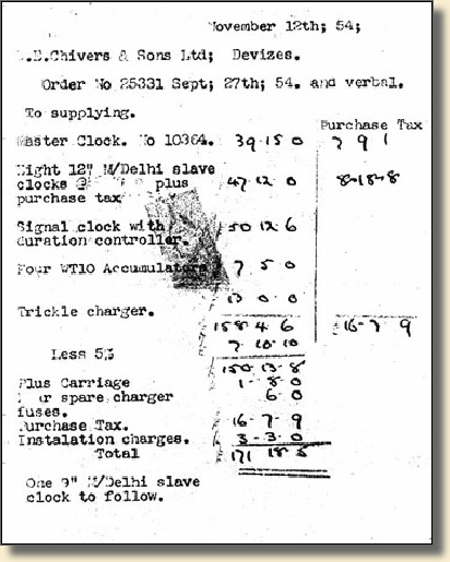
Fig. 21
Bill of Sale 1954
Based on inflation since 1954, the system would be priced around £3000 in 2002.
The following master clock price comparison is based on old price lists (excluding Purchase Tax) from the various companies:
| ECS | £39-15-0 |
| Synchronome | £36-10-0 |
| Gents | £31-0-0 |
The ECS price is from the invoice above (1954).
The Synchronome price is from a 1951 price list. (The Synchronome price in 1954 would have been very similar.)
The Gents price is calculated, based upon a comparison of 1970 price lists, where the Gent price is about 15% cheaper than the Synchronome in that year.
CONCLUSIONS
The 63 clocks recorded in the survey span the various serial number ranges fairly evenly and fit the production pattern graph quite smoothly (Chart 1). It is not thought that there was a significantly larger number of clocks produced than has been suggested in that chart. As the serial numbers are not continuous over the various series, the total number of clocks shown on the left hand vertical axis of Chart 1 has been calculated by assuming that the number of clocks made in each series is given by the highest serial number recorded in that series.
The only serial number change to coincide with design changes is that from 10,000 to 20,000. Perhaps the other serial number changes were intended to confuse competitors regarding the numbers of clocks made.
The ECS master clock was one of the last of its type to reach the market and it needed to compete with the well established makes, primarily of Gents and Synchronome, both of whom had already been selling their master clocks for several decades. Gents produced an average of 360 clocks per year over the period from 1945 to 1960, and Synchronome produced around 160 to 200 clocks per year over the same period. English Clock Systems Ltd appear to have produced an average of 83 clocks per year of the double-contact version from 1945 to 1960, which dropped to an average of only 50 clocks per year from 1960 (after the introduction of the improved single-contact version) to 1966 which is the last recorded clock in the survey. In its early life, the ECS was also the most expensive of the three.
Although the quality of manufacture of the ECS master clock was mainly sound, there were design flaws. It did not introduce any major new technical innovation, and it proved to be less reliable than its competitors, due largely to the double-contact arrangement. Service record cards that have survived with three clocks in the survey show that, on average, three or four service calls were made each year with some years requiring six calls. There is one example of eleven calls in a calendar year.
The introduction of the improved single-contact version seems to have been too little too late to save the future of the clock.
SUMMARY CHARTS
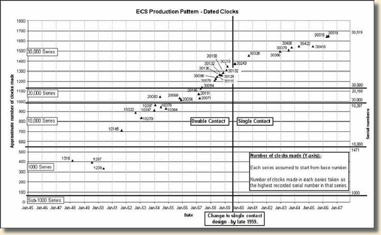
Chart 1
Dating information is predominantly derived from a date code on the pilot dial.
Click here for a full-size image of Chart 1.
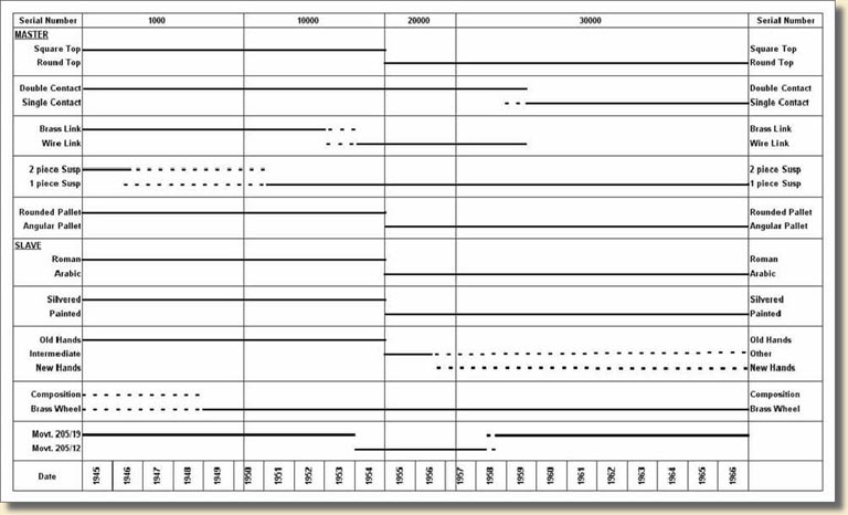
Chart 2
Design Changes
.
Click here for a full-size image of Chart 2.