
ECS 1-Second Master Clock Set-Up Notes
| Printer friendly Page |
Within this page, fast-find:- |
|
|
|
|
|
|
ADJUSTMENTS TO 1-SECOND MASTER CLOCK (DOUBLE CONTACT)
1. Disconnect Slave clock circuit from Master clock.
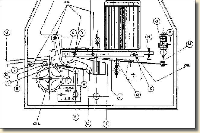
2. Ensure that the pendulum is hung squarely across the case and that it is neither too far forward so that the click jewel S and jewel securing wire rub on the back of the Escape (Count) Wheel nor too far backward so that the click jewel S and jewel securing wire rub on the Lever F.
3. When in correct position, the impulse plate C when swinging should run exactly in line with the Gravity lever roller D. In other words the roller or Impulse plate should not overlap each other. If necessary, the Impulse plate call be moved round the pendulum by slackening the securing screw. Tighten the pendulum trunnion clamp wing nuts.
4. Ensure that with the pendulum stationary, the shoulder of the impulse Plate is exactly in line with the pivot of the roller D, as shown in drawing. To obtain this setting the pendulum can be moved to the left or right along the trunnion. The gap between roller D and Impulse plate C should be .005".
5. With the pendulum stationary the click jewel S should be midway between two teeth of the escape wheel as shown in drawing. If the jewel is closer to one tooth than the other, the back stop wire L can be adjusted for length so that the back stop B moves the escape wheel in a clockwise or anti-clockwise direction. Keep the escape wheel lightly pressed to the back stop when making this adjustment.
6. The jewel S should be adjusted by turning the click wire A pivot bush in the Impulse plate. The bush should be adjusted for depth of engagement so that the jewel moves the escape wheel just sufficiently to allow the back- stop to drop behind each tooth of the escape wheel with the minimum amount of backlash. Move the pendulum slowly by hand to check this.
7. The release wire R.L. should be almost touching the catch G prior to releasing the catch, as shown in drawing, the wire can be bent to obtain this position. The length of the release wire is adjustable and it should be set so that it moves lever G just sufficiently to unlatch the Gravity Lever H.
8. With the gravity lever H resting on the catch G, the air gap between the two magnet poles should be between .025" and .030". This can be obtained by slightly bending the flat gravity lever suspension spring R either up or down as required.
9. With the Gravity Lever H held up to the felt buffer the distance between the Gravity Lever suspension spring R and stop on Catch G should be 1/16". Adjust buffer (above) gravity lever suspension spring, to obtain this adjustment.
10. Ensure that the armature flat spring, securing contacts T and screwed to armature J is perfectly straight. Turn Contact break screw N so that the head of the screw is well away from the armature flat spring when the armature is held up by the Gravity Lever.
11. Unlock the two Pillar Contact nuts P and turn the front Pillar Contact O up several turns. Hold armature J up to Gravity Lever H and turn back Pillar Contact O up or down so that the Pillar Contact only just touches the contact plate T. Tighten locknut P. Adjust the front contact likewise.
12. Reconnect the Slave clock circuit. Connect milliampere meter to Pillar Contact Screws O and adjust line current to .32 amperes (320 milliamps) by moving the lower clip of the resistance in the top left hand corner of the Master Clock Case. Disconnect meter after setting line current.
13. Set control lever E over to position A (advance) and set the pendulum swinging. When the Plate Contacts T touch the Pillar Contacts Screw O, the circuit should be made and the Gravity Lever replaced on the catch G. If the Gravity Lever is not replaced on the catch it will be because the front Pillar Contact screw requires turning up or down until a contact is made, this is just a rough adjustment. To finally adjust the contacts, carefully carry out the following:-
- Keep pendulum swinging. Turn front Pillar Contact screw upwards slowly until Gravity arm H fails to return to step on catch G without assistance from the pendulum.
- Note position of Pillar Contact screw.
- Now turn the screw downwards until once again the Gravity arm H fails to return to the step on catch G without assistance from the pendulum. Again note position of Pillar Contact screw O.
- Turn screw O up again to midway position i.e. midway between the high position when the clock failed and the low position when the clock failed. Hold Pillar contact screw in this position and tighten locknut P. Return Lever E to N position.
14. It should now only be necessary to check for contact break adjustment. To do this release catch G and lower Gravity arm H slowly with the left hand and move the pendulum to the right with right hand. When Contacts M are made, hold pendulum in this position and allow Gravity arm H to rise slowly until contacts M are broken. The position of the Gravity arm suspension spring R relative to the step on catch G should then be noted. The gap is set at 3/32" to 1/8" - alter screw to obtain this adjustment.
15. Set the line current to 0.26 amps (260 milliamps) by moving the lower clip of the resistance in the top left hand corner of the Master clock case. Set control lever E over to position A advance and set the pendulum swinging. The Magnet Coils should just manage to lift the armature and gravity lever to the catch without any assistance from the pendulum. Adjust buffer capstan screw Q to obtain this setting.
16. Readjust the line current to normal setting i.e. 0.32 amps (320 milliamps) and disconnect meter. Make sure all screws etc. are tightened.
17. Set all Slave clocks and Master Clock pilot dial to same time.
ADJUSTMENTS TO 1-SECOND MASTER CLOCK (SINGLE CONTACT)
1. Disconnect slave clock circuit from Master Clock.
2. Make sure that the pendulum is hung squarely across the case and that it is neither too far forward so that the click jewel S and jewel securing wire, rub on the back of the Escape (Count) Wheel nor too far backward so that the click jewel S and jewel securing wire, rub on the lever F.
3. When in correct position, the Impulse Plate C when swinging should run exactly in line with the Gravity Lever roller D. In other words, the roller or Impulse Plate should not overlap each other. If necessary the Impulse Plate can be moved round the pendulum by slackening the securing screw. Tighten pendulum trunnion clamp wing nuts.
4. Make sure that with the pendulum stationary the shoulder of the Impulse Plate is exactly in line with the pivot of the roller D as shown in drawing. To obtain this setting the pendulum can be moved to the Left or right along the trunnion. The gap between the roller D and Impulse Plate C should be .005".
5. With the pendulum stationary the click jewel S should be midway between two teeth of the escape wheel as shown in the drawing. If the jewel is closer to one tooth than the other, the escape wheel can be moved in a clockwise or anti-clockwise direction by adjusting the length of the back-stop wire L and bead B. Keep the escape wheel lightly pressed to the back-stop when making this adjustment.
6. The jewel S should be adjusted by turning the click wire A pivot bush in the Impulse Plate. The bush should be adjusted for depth of engagement so that the jewel moves the escape wheel just sufficient to allow the back stop to drop behind each tooth of the escape wheel with the minimum amount of backlash. Move the pendulum slowly by hand to check this.
7. The release wire R.L. should be almost touching the catch G prior to releasing the catch, as shown in the drawing; the wire can bent to obtain this position. The length of the release wire is adjustable and it should be set so that it moves lever G just sufficient to unlatch the Gravity lever H.
8. With the gravity lever H resting on the catch G, the air gap between the two magnet poles should be between .025" and .030". This can be obtained by slightly bending the flat gravity lever suspension spring R either up or down as required.
9. With the Gravity Lever H held up to the felt buffer the distance between the gravity lever suspension spring R and step on catch G should be 1/16". Adjust buffer above gravity lever suspension spring to obtain this adjustment.
10. Make sure that the armature flat spring securing contact T and screwed to armature J is perfectly straight. Turn contact break screw N so that the head of the screw is well away from the armature flat spring when the armature is held up to the gravity lever.
11. Unlock Pillar contact nut P. Hold armature J up to gravity lever H and turn pillar contact screw O up or down so that the Pillar Contact only just touches the Contact plate T. Tighten locknut P.
12. Re-connect the slave clock circuit and set line current to .32 amps (320 milliamps).
13. Check for contact break adjustment. To carry this out release catch G and lower gravity arm H slowly with the left hand and move the pendulum to the right with the right hand. When contacts M and T are made, hold pendulum in this position and allow gravity arm H to rise slowly until contacts M and T are broken. The position of the Gravity Lever suspension spring R relative to the step on the catch G should then be noted. The suspension spring should be 3/32" to 1/8" down the catch from the step. Alter the position of the contact break screw N to obtain this setting.
14. Set the line current to 0.26 amps (260 milliamps) by moving the lower clip of the resistance in the top left hand corner of the Master clock case. Set control lever E over to position A advance and set the pendulum swinging. The Magnet Coils should just manage to lift the armature and gravity lever to the catch without any assistance from the pendulum. Adjust buffer capstan screw Q to obtain this setting.
15. Readjust the line current to normal setting i.e. 0.32 amps (320 milliamps) and disconnect meter. Make sure all screws etc. are tightened.
16. Set all slave clocks and Master Clock Pilot Dial to the same time.